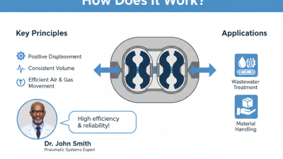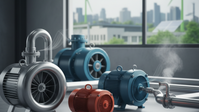
A Roots Blower is a positive-displacement machine that moves air through two counter-rotating lobes. Its working principle looks simple. The engineering is not.
Inside the casing, the lobes rotate without touching each other or the housing. Air enters the inlet, fills the spaces around each lobe, and travels toward the discharge side. Pressure rises when downstream resistance pushes air back against the delivered volume. Unlike a screw compressor, a Roots Blower creates little internal compression. Most compression occurs outside the casing. This distinction affects temperature, efficiency, noise, and system design. Small clearances are critical.
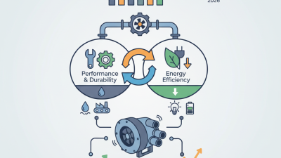
The U.S. Department of Energy’s Improving Compressed Air System Performance sourcebook reports that compressed air may consume about 10% of industrial electricity. That figure explains why blower selection deserves more than a catalog comparison. A poorly matched unit can waste power through excessive pressure, leakage, or unnecessary throttling. The same sourcebook emphasizes system-level assessment, not equipment efficiency alone. ISO 1217 also provides recognized methods for measuring compressor performance, including flow, pressure, and power. These references improve reliability, but field results still depend on installation conditions.
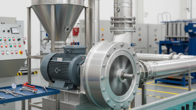
Roots blowers support wastewater aeration, pneumatic conveying, and industrial gas handling. In a treatment basin, the blower’s steady airflow keeps diffuser bubbles active beneath the water surface. In a conveying line, pressure must overcome material resistance and distance. Not every installation rewards maximum airflow. That assumption can be costly. This guide examines how a Roots Blower works, where its losses occur, and which technical details deserve careful review before purchase.
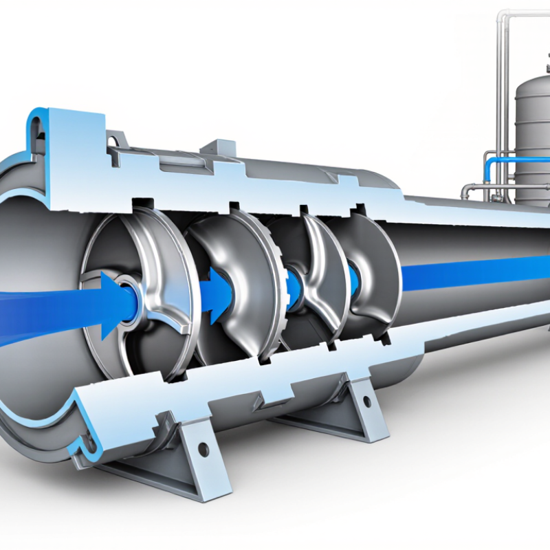
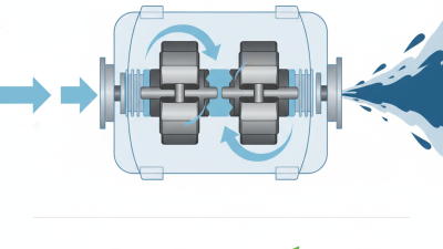
A Roots blower is a positive-displacement machine designed to move a measured volume of air. Its casing usually contains two counter-rotating rotors with two or three lobes. The lobes do not normally touch. Small clearances keep them separated while timing gears maintain their alignment.
As the rotors turn, air enters the inlet and fills spaces between each lobe and the housing. The rotating lobes carry these trapped air pockets toward the outlet. The blower does not create much internal compression. Instead, pressure develops when the outlet system resists the incoming air. That detail is easy to miss.
The operating principle looks simple. Real installations are less forgiving. Clearances, rotor timing, temperature, and speed strongly affect performance. A tiny clearance error can increase internal leakage. Excessive speed may raise heat, noise, and power demand. The machine can also produce noticeable pressure pulsation, especially with two-lobe rotors.
A three-lobe design often provides smoother delivery, but it is not automatically more efficient in every application. Engineers must check flow rate, pressure ratio, inlet temperature, and duty cycle together. Lubricated bearings and timing gears usually remain isolated from the air path. Routine inspection should look for unusual vibration, oil leakage, rising discharge temperature, and damaged filters.
The basic explanation is useful, but incomplete. Real performance depends on the entire system, not the blower alone.
A Roots blower is a positive-displacement air mover. Its two rotors turn in opposite directions inside a closely machined housing. The rotors do not normally touch. Tiny clearances are essential, though they make the machine sensitive to heat, dust, and incorrect alignment. Air enters through the inlet, fills the spaces between each rotor and housing, then moves toward the outlet. Pressure rises when the trapped air meets resistance downstream.
The rotors are the working core. Their lobes must remain accurately phased as they rotate. Timing gears maintain this relationship without allowing metal-to-metal contact. Even a small timing error can cause noise, heat, or rotor damage. The housing forms the air path and controls the clearances around the lobes. It must remain rigid, because distortion can reduce efficiency. A good inspection checks for scoring, uneven wear, and signs of overheating.
Bearings support the rotor shafts and manage radial and axial loads. Excessive play can change the rotor position and produce vibration. Seals protect the bearing chambers and limit air or oil leakage. They are small parts, but their failure can spread quickly. In practical maintenance, technicians should examine gear backlash, lubricant condition, shaft movement, and seal surfaces together. Replacing one component alone may not solve the problem. This is where the design becomes less forgiving. Clearance measurements should follow the manufacturer’s service limits, since visual checks cannot reveal every issue.
A Roots blower moves air through repeated rotor-pocket displacement. Two shaped rotors turn inside a close-fitting housing, usually with synchronized timing gears. As a pocket passes the inlet, it opens to atmospheric air and captures a nearly fixed volume. The pocket then carries that air around the housing toward the outlet. Simple and mechanical.
The phrase “fixed volume” needs care. It describes geometric displacement, not guaranteed delivered airflow. For each revolution, the theoretical flow equals displacement per revolution multiplied by rotational speed. Actual flow falls because of internal slip, inlet losses, temperature, and clearance changes. A 100-liter-per-revolution machine running at 1,000 revolutions per minute has a theoretical capacity of 100 cubic meters per minute. The real figure is lower.
The rotors do not normally compress air inside the pocket. They transport it. Pressure rises when transported air meets the downstream system, causing brief reverse flow across rotor clearances. That process creates pulsation and heat. The U.S. Department of Energy reports that compressed-air systems commonly consume 10–15% of industrial electricity, so small airflow errors can carry meaningful energy costs. Its industry sourcebook also identifies leakage as a frequent loss, often reaching 20–30% in poorly maintained systems. Actual performance depends heavily on operating conditions. That is the uncomfortable part. A clean theoretical calculation may look precise, yet field measurements can disagree. Inlet filters, piping, and receiver volume deserve attention, not just rotor speed.
Each revolution of the rotors carries a nearly fixed pocket volume from the inlet to the outlet. This chart models a 1.0 L displacement per revolution and compares theoretical intake flow with an estimated 90% volumetric efficiency.
Reading the chart: Theoretical flow increases almost linearly with rotor speed because each revolution moves the same volume. In practice, leakage, heating, pressure difference, and inlet restrictions reduce the delivered flow.
What Is a Roots Blower and How Does It Work?
A Roots blower is a positive-displacement machine with two synchronized lobes inside a close-fitting casing. The lobes rotate without touching each other or the housing. Air enters the inlet, fills pockets between the lobes, and travels toward the discharge port. The blower moves a nearly fixed volume during each revolution. It does not normally compress that trapped air internally.
The pressure rise comes from backflow. When a lobe pocket reaches the discharge opening, it meets air already held at a higher pressure. That compressed air briefly flows backward into the pocket. The incoming air is then equalized almost instantly, creating compression outside the pocket rather than during transport. This event produces the blower’s characteristic pressure pulses and sound. The process is simple, but not gentle.
Small clearances are essential. They limit contact while reducing leakage across the lobes and casing. Higher discharge pressure increases backflow, heating, power demand, and leakage. A pressure gauge may show stable average pressure, while the internal flow remains strongly pulsating. That difference matters during troubleshooting.
In a practical inspection, hot discharge piping or unexpected vibration can indicate excessive pressure or poor flow control. A Roots blower is often described as oil-free in the air path, yet bearings and gears still require correct lubrication. I once viewed the “no internal compression” explanation as complete. It is useful, but incomplete. Backflow, clearance leakage, and heat decide how the machine behaves in real service.
What Is a Roots Blower and How Does It Work?
A Roots blower uses two counter-rotating lobes to move a fixed volume of gas. The lobes do not compress gas internally. Instead, they carry air toward the discharge, where system pressure creates compression. This simple design offers steady flow, but performance changes sharply with operating conditions.
Published industry data commonly places Roots blower efficiency around 70–90% at suitable flow and pressure ratios. The U.S. Department of Energy’s Improving Compressed Air System Performance sourcebook warns that efficiency falls when pressure exceeds the design point. CAGI performance guidance also emphasizes testing at defined inlet conditions, speed, and discharge pressure. These details matter. A headline efficiency figure can mislead.
Heat is unavoidable. Discharge air may become noticeably hot because compression occurs against downstream resistance. Internal leakage, called slip, increases as clearances widen or pressure rises. The European Commission’s Best Available Techniques reference materials identify pressure losses and poor control as major energy penalties in compressed-air systems. Roots blowers also have practical pressure limits; exceeding them can overload bearings, seals, and drive motors. Field checks should record inlet temperature, outlet temperature, flow, power, and pressure together. Otherwise, the data remains incomplete. My own caution is simple: 70–90% is a useful benchmark, not a promise. Two identical-looking machines can perform differently after wear, fouling, or poor control settings.
| Performance Dimension | Typical Value or Range | What It Means | Engineering Notes |
|---|---|---|---|
| Operating principle | Positive-displacement rotary lobe | Two counter-rotating lobed rotors trap and transport a nearly fixed volume of gas per revolution. | The rotors normally do not touch; timing gears maintain the required clearance. |
| Volumetric efficiency | Approximately 80–95% | Indicates how closely the actual inlet flow approaches the theoretical swept volume. | Clearance leakage, pressure ratio, gas temperature, and rotor speed strongly affect this value. |
| Overall efficiency | Approximately 70–90% | Represents useful gas power divided by shaft input power under suitable operating conditions. | The upper end is more likely near the design point; efficiency falls at low flow, high pressure ratio, or excessive speed. |
| Typical flow range | About 50–30,000 m³/h | Covers small laboratory and pneumatic units through large industrial machines. | The actual capacity is determined by displacement per revolution and operating speed. |
| Common rotational speed | Approximately 1,000–4,000 rpm | Higher speed generally increases flow, but also increases noise, friction, leakage effects, and heat. | The permitted speed is limited by rotor balance, bearing life, temperature, and drive power. |
| Typical continuous pressure differential | Approximately 0.3–1.0 bar | This is a common continuous operating range for standard industrial blower service. | Higher pressure differentials require specially rated designs and may substantially reduce flow and efficiency. |
| Typical maximum pressure differential | Approximately 1.0–1.5 bar for many standard designs | Exceeding the rated differential can cause excessive temperature, power demand, and mechanical stress. | The manufacturer’s pressure, speed, and temperature limits must always take priority over generic ranges. |
| Typical vacuum capability | Approximately 0.3–0.7 bar vacuum | Roots blowers can be used for vacuum service when designed and cooled for the required vacuum level. | Deep-vacuum operation may require a backing pump, staged compression, or a booster arrangement. |
| Discharge temperature rise | Approximately 30–100°C above inlet temperature | Gas temperature increases because compression occurs mainly through backflow and downstream system resistance. | Temperature rise increases rapidly with pressure differential, restricted discharge, and inadequate cooling. |
| Heat generation | Most input power becomes heat | Mechanical losses, gas friction, leakage, and pressure-related work are converted primarily into heat. | Oil lubrication, bearing condition, ventilation, and discharge cooling influence the final temperature. |
| Internal leakage or slip | Typically 5–20% of theoretical displacement | Gas moves backward through clearances from the discharge side toward the lower-pressure inlet side. | Slip increases with pressure differential, worn components, high gas temperature, and excessive clearances. |
| External leakage | Should be negligible in a properly maintained unit | Leakage may occur at shaft seals, casing joints, pipe connections, or relief devices. | External leakage is a maintenance issue and should not be confused with normal internal slip. |
| Pressure pulsation | Low to moderate; system-dependent | Periodic pocket release produces flow and pressure fluctuations at the discharge. | Silencers, pulsation dampers, flexible connectors, and correctly sized piping can reduce vibration and noise. |
| Noise level | Approximately 75–100 dB(A) before acoustic treatment | Noise comes from rotor meshing, gas pulsation, bearings, drive components, and discharge flow. | Measured sound level depends on distance, enclosure, operating point, and inlet or outlet silencing. |
| Gas-contacting lubrication | Normally oil-free in the compression chamber | The conveying chamber is generally separated from lubricated bearings and timing gears. | Oil may still be present in gear or bearing housings, depending on the design. |
| Power requirement | Approximately 5–500 kW | Required shaft power increases with mass flow, pressure differential, gas density, and mechanical losses. | A relief valve or control system is essential to prevent overload during blocked or restricted discharge conditions. |
| Response to speed change | Flow is approximately proportional to speed | Increasing speed generally increases the theoretical displacement and delivered flow. | Actual flow does not rise perfectly linearly because leakage, heating, and system pressure also change. |
| Best operating region | Near the rated flow and pressure point | Operating near the design point generally provides the best balance of efficiency, temperature, noise, and service life. | Continuous operation at the pressure limit should be avoided unless specifically approved for the selected configuration. |